Read and Send SMS using SIM800L GSM Module and Arduino
April 28th, 2019 by cedcraftscodes

Today we will learn how to send and receive SMS with SIM800L GSM Module and Arduino. This is a great project that you can integrate with your home automation or send sensor readings to your phone using SMS.
Requirements
Arduino
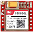
Sim 800L GSM Module
Simcard with Load for Texting
Connections
Connect VCC pin to 5V. Sim 800L recommended voltage is 3.4V to 4.4V but it can handle up to 5V of Arduino. You can use a linear Voltage regulator like LM317 or LM388 or just use a Buck Converter to step down the voltage. In this tutorial, we won’t be using those and will directly connect our module to 5V.
Connect the RX to Digital Pin 2 and TX to Digital Pin 3. Lastly, connect the GND to GND of Arduino.

After connecting the SMS module, plug your Arduino to your PC.
You will notice that the SMS module is Blinking. If it is blinking every 1 second, it means that the module is running but hasn’t made a connection to the cellular network yet. If it blinks every 3 seconds, the module has made contact with the cellular network & can send/receive voice and SMS.
Source Code
Sending SMS
1 2 3 4 5 6 7 8 9 10 11 12 13 14 15 16 17 18 19 20 | #include <SoftwareSerial.h> SoftwareSerial mySerial(3, 2); void setup() { mySerial.begin(9600); delay(1000); mySerial.println("AT"); delay(500); mySerial.println("AT+CMGF=1"); delay(500); mySerial.println("AT+CMGS=\"+YYxxxxxxxxxx\"\r"); delay(500); mySerial.print("Hello World from Dev Craze!"); delay(500); mySerial.write(26); } void loop() { } |
Change the YY with your country code, and continue with your number. For example, in the Philippines, YY would be 63 and X’s would be the next 10 digits.
For the complete country codes, visit this website. http://www.ipipi.com/help/telephone-country-codes.htm
AT is the abbreviation of “Attention“.
| AT | Perform handshake. Replies OK if succeeded. |
| AT+CMGF=1 | Set the operating mode to SMS text mode |
| AT+CMGS=”+YYxxxxxxxxxx” | Send the Message |
You will notice that we added mySerial.write(26); (number 26 (1A hex) This is to print Ctrl+Z, by convention often described as ^Z to send the message.
Reading Message
Upload the following code to your Arduino
1 2 3 4 5 6 7 8 9 10 11 12 13 14 15 16 17 18 19 20 21 22 23 24 25 26 27 28 29 30 31 32 33 | #include <SoftwareSerial.h> SoftwareSerial mySerial(3, 2); void setup() { Serial.begin(9600); mySerial.begin(9600); Serial.println("Starting..."); delay(1000); mySerial.println("AT"); pollSms(); mySerial.println("AT+CMGF=1"); pollSms(); mySerial.println("AT+CNMI=1,2,0,0,0"); pollSms(); } void loop() { pollSms(); } void pollSms() { delay(500); while (Serial.available()) { mySerial.write(Serial.read()); } while(mySerial.available()) { Serial.write(mySerial.read()); } } |
After uploading the code, open up your Serial Monitor by clicking “Tools -> Serial Monitor” or simply “CTRL + SHIFT + M”. Send a message to your GSM module and you will see the ff. in your Serial Monitor.
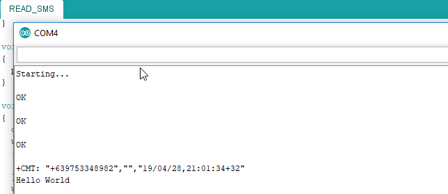
The AT+CNMI=1,2,0,0,0 sets how the modem will response when an SMS is received. We will need to continuously poll the serial to monitor the message.
Testing your GSM Module
If you want to test your GSM module connected to your Arduino, there is a handy tool called AT Command Tester.

Simply choose the COM Port of your Arduino and set the Baud Rate to 9600 then connect. You can test the GPRS connection, sending/receiving of message, calls, get information about your module and many more 🙂
If you have further concerns or would like to integrate the GSM module with your sensors, just comment down below and I will promptly reply to your comment.
Please like and share if you enjoy this tutorial 🙂
Related Posts

Publishing Java SpringBoot Library in JitPack

Deploy React Application in Netlify

MFRC522 RFID Read and Write Data in Specific RFID Block

Create a BadUSB Rubber Ducky using Arduino

Social Media Phishing with Captive Portal using NodeMcu

Scan WordPress site Vulnerabilities using WPScan


Comments
6 Comments
Leave a Reply
Recent Posts

serhat
August 18, 2019 at 5:08 amHi, thank you for your share
i cannot see anything in my serial monitor. Only showing “Starting…” whats is teh problem?
cedcraftscodes
August 18, 2019 at 9:36 amCan you provide what baud rate selected in your Arduino Ide? Also, you may want to check your connection if it is interfaced properly.
Nass
October 22, 2019 at 2:35 pmThanks for your effort. I sent sms to sim800l and want to read it by arduino code that to make some processes by arduino codes.
Could u advices.
BR.
cedcraftscodes
November 23, 2019 at 7:55 pmYes, it will still work! You just need to change the URL, point it to your web server uploaded online.
selma
September 1, 2020 at 4:33 amhow can i controll steper motor with gsm sim800l
Godwin
September 8, 2022 at 12:14 pmHow can I code capacitive soil moisture sensor and sim800l GSM module with Arduino so that the sensor readings is sent as an SMS to a specific number.